DXF for CNC: kerf compensation, explained.
Send a vector to a CNC router without kerf compensation and the cut comes out the wrong size. By how much? By the kerf — the width of material the tool removes. For a 1/4-inch bit, that is roughly 6mm of slop you did not account for. Here is the whole problem.

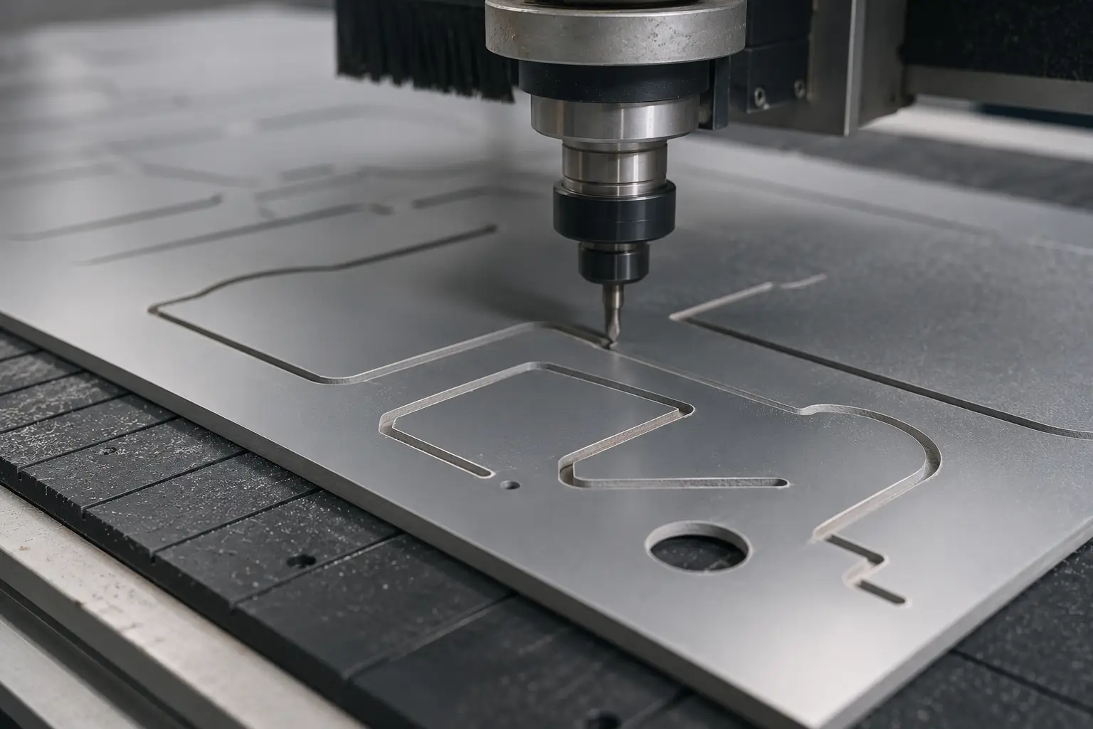
What kerf is
Every cutting tool removes material on both sides of the path it follows. A 1/4-inch endmill carves a 6.35mm-wide channel. Your vector path is a centerline; the actual cut takes material away from both sides of that line.
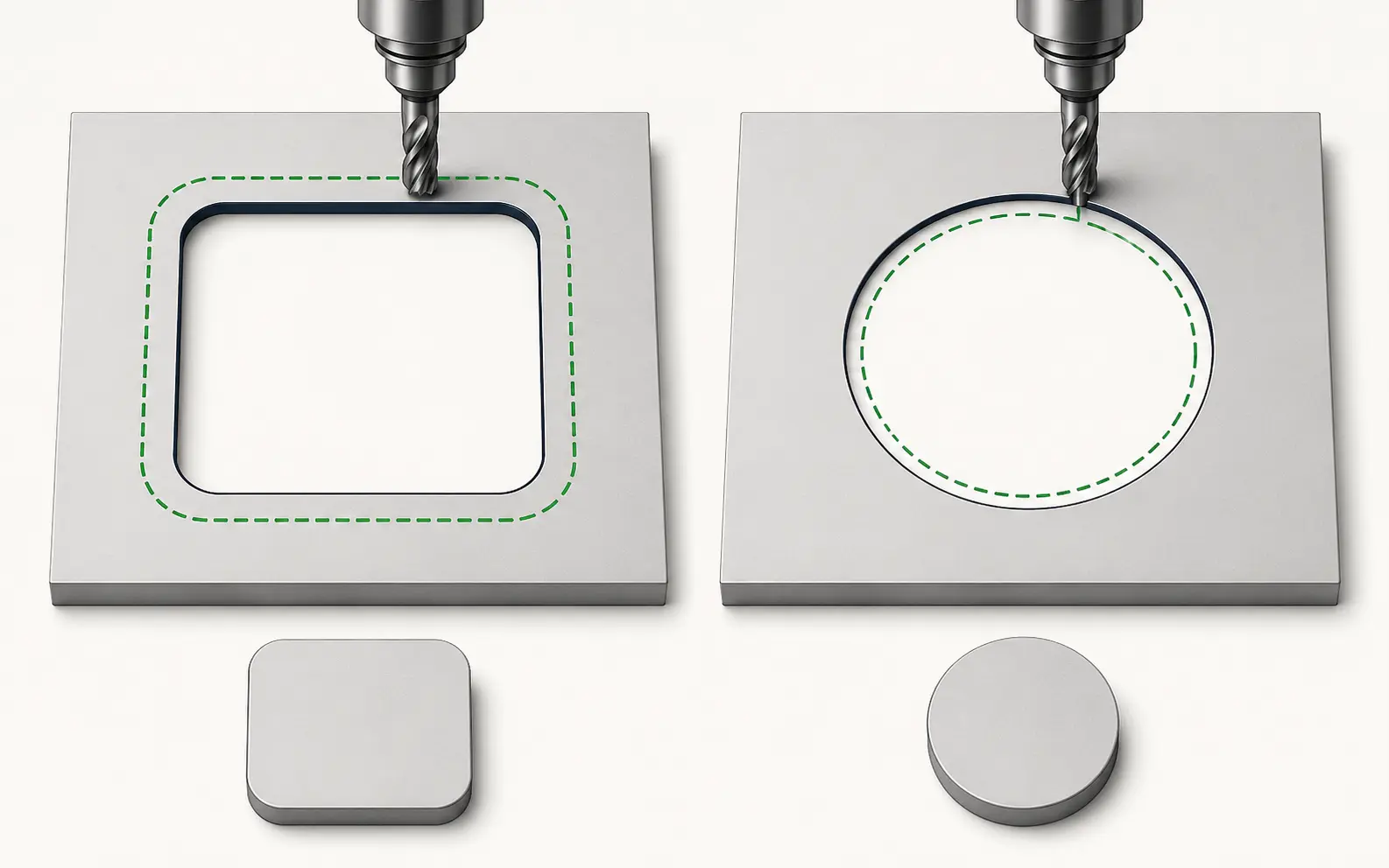
Inside cut vs outside cut
For holes (an inside cut), the tool needs to travel inside the vector line — offset the path inward by half the kerf so the resulting hole matches the vector. For outer edges (an outside cut), the tool travels outside the line — offset the path outward by half the kerf so the resulting part matches.
Kerf-compensated paths
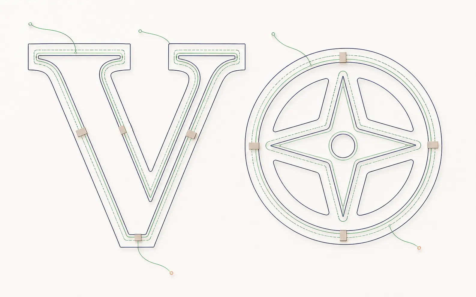
A properly prepped DXF has the offset baked in. Outer edges have grown by half-kerf; inner holes have shrunk by half-kerf. The CAM software just follows the path directly with no compensation. We deliver this by default for 1/4-inch and 1/8-inch tooling on aluminum, acrylic, and MDF.
Tool diameter and material matter
A 60W CO2 laser on 3mm acrylic has a ~0.2mm kerf. A 1/8-inch endmill on 1/2-inch aluminum has a 3.175mm kerf. We ask for both when you order — material thickness and tool diameter — and adjust offsets accordingly.
Kerf-compensated, CAM-ready paths. Redrawn by hand for your machine.
Inside and outside cuts, correct tool offset, clean layers your CAM reads on the first import — production-correct in 24 hours.
Need something custom? Email hello@vectorwiz.com
Lead-ins and tabs
For larger parts, we add lead-in arcs (the tool enters the path at a tangent, not perpendicular) and bridge tabs (small uncut sections that hold the part in place until you remove it). These are CAM features that ride on top of the kerf compensation.
Layer naming for CAM
CUT THROUGH, SCORE / FOLD, ENGRAVE — each layer named for the operation. CAM software (LightBurn, VCarve, Fusion 360) lets your operator assign a tool path to each layer in seconds. See CNC service →
Frequently asked questions
What is kerf compensation?
Offsetting the cut path by half the width of the tool so the finished part matches the drawing. The tool removes material on both sides of the line it follows, so an uncompensated path cuts every part undersized on the outside and oversized on the inside.
Do I offset inward or outward?
Both, depending on the feature. Inside cuts such as holes offset inward by half the kerf so the hole ends up the drawn size; outer edges offset outward by half the kerf so the part ends up the drawn size. Getting these backwards is the classic scrapped-part mistake.
What kerf value should I use?
It depends on the tool and material — a CO2 laser on thin acrylic removes a fraction of a millimetre, while a quarter-inch endmill removes over 6mm. Tell us the tool diameter and the material thickness with your order and we bake the correct offset into the DXF.
Doesn't the CAM software handle kerf?
It can, and many shops let it. The risk is doubling up — if the file is already compensated and CAM applies its own offset, the part comes out wrong. A pre-compensated DXF removes the ambiguity; just tell your operator the offset is already in the file.
What DXF version and units should I send?
Confirm both with the shop running the job. Many CAM workflows want an older, widely-compatible DXF dialect, and units have to be explicit — a file interpreted in inches instead of millimetres is off by a factor of 25.4. We deliver to the version and units you specify.
Naimur Rahman
Leads design direction and quality at VectorWiz. Reviews and redraws production artwork by hand across sign, screen-print, embroidery, and CNC work.
Related articles
Drawn by hand. Built for production.
Instant pricing, no commitment. Production-correct vectors in your inbox in 24.